Introduction
The numerous bridge collapses that have occurred in recent years show the need to implement SHM systems that provide continuous, real-time information on the condition of these structures. In addition to preventing disasters, our advanced SHM methodology allows a very significant reduction in the current investment in maintenance and repair thanks to its predictive capability.
Since 2000 the Chilean Ministry of Public Works has carried out the instrumentation of some bridges, but it was not until 2019 that they have moved towards a disruptive approach, demonstrating an advanced understanding of the importance of implementing a predictive maintenance strategy for bridges based on Artificial Intelligence and mathematical modelling. Thus, the Dirección de Vialidad is working to achieve this necessary paradigm change, which in turn is aligned with the creation of a National Policy on Artificial Intelligence that will contribute to the technological transition in this country.
In this article we want to show how, through our innovative methodology based on the creation of a Digital Twin for each bridge combined with advanced probabilistic algorithms for predicting the evolution of damage, it is possible to identify, quantify and predict the evolution of existing damage in order to have a complete understanding of the present and future structural condition. This will facilitate decision-making, including the optimum design of structural reinforcements taking into account both technical and economic criteria, and checking their compliance through the simulation of different potential scenarios.
To illustrate the case, we will explain how this functionality was used in a case study, more specifically in the Calle Calle bridge in Chile.
Development of a Digital Twin for the Calle Calle Bridge
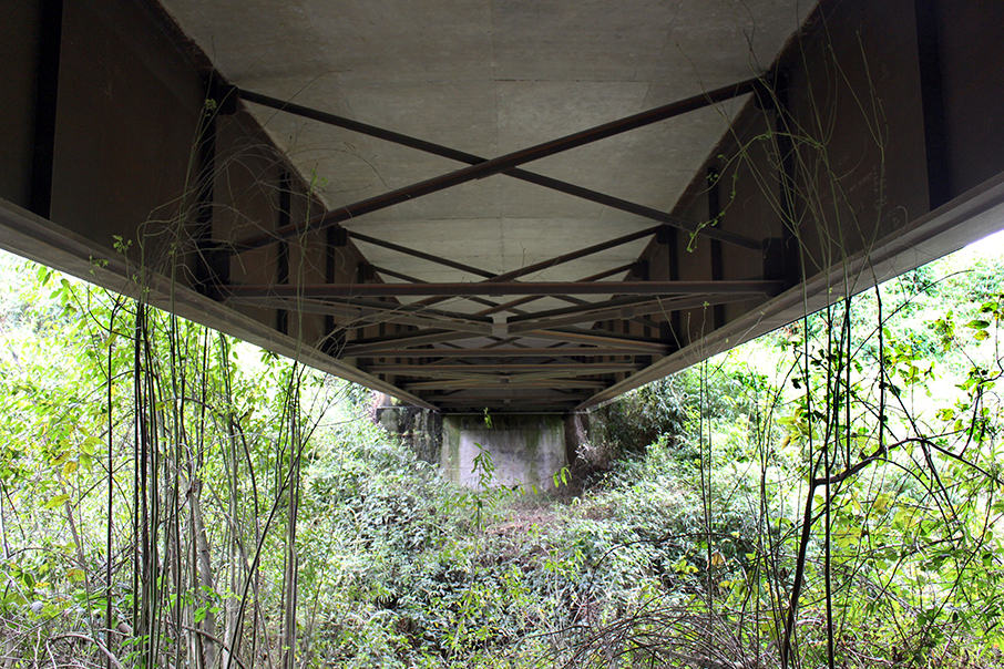
The Calle Calle bridge is located at PK 53.94 on Route U-91 in the southern Chilean region of Los Lagos. The bridge has a total length of 37.30 meters, with a single isostatic span, and a total width of 8.60 meters, including two lanes of 3.5 meters width each and two pedestrian path of 0.8 meter width each.
The structure has a mixed deck of 20-cm thick reinforced concrete collaborating slabs and two double T-shaped longitudinal reinforced beams with varying lower flanges with a total edge of 1.78 metres.

Figure 1. Calle Calle Bridge. Side view
The longitudinal beams are connected to each other by means of reinforced concrete diaphragms in the sections on supports and St. Andrew’s Cross triangulations with a lower horizontal beam, formed by L-section and double L-section profiles, respectively.

Figure 2. Calle Calle Bridge. Bottom view.
The substructure is composed of reinforced concrete closed abutments with a front retaining wall (4.7 meter long and 8.55 meter wide) and open wing wall at the bottom. With regard to the resistant performance of the structure, its main mechanism of resistance to vertical loads is flexural mechanism.
In 2019 the Ministry of Public Works detected the need to diagnose the structural health of this bridge, for which our methodology was implemented.
As explained in our SHM section, after an initial registration we developed an advanced numerical model of the bridge in which we represent the structural elements and their connections. This preliminary model allows us to determine which sensor nodes are necessary and their locations to get the registers to validate and calibrate the model. The continuous recording carried out by the sensors installed by our engineers allows the permanent updating of the model, providing a Digital Twin of the bridge for the diagnosis of both present and future structural health.
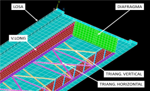
Figure 3. 3D model of the Calle Calle bridge. Structural elements.
For this bridge we first carried out a diagnosis of the condition of the structure (which we call the Primary Diagnosis). The Primary Diagnosis is a diagnosis at a specific time, and consists of the comparison of the values of the structural health parameters (measured and/or calculated) with the limits (normative and/or structural) of these parameters. Thus, through the treatment of the records obtained together with the numerical model of the structure, and the comparison with the admissible limits of variation of the monitored parameters, it could be concluded that the structure is in an ACCEPTABLE condition. This means that the integrity of the structure is NOT imminently compromised.
Once the Primary Diagnosis of the Calle Calle Bridge was completed, our methodology was used to simulate highly demanding scenarios, which allows us to know in advance the sections that could present failures when subjected to specific solicitations. This kind of diagnosis is what we call Advanced Structural Diagnosis.
Results of the Advanced Structural Diagnosis of the Calle Calle Bridge
The Advanced Structural Diagnosis reveals the structural performance of the bridge, based on the calculation of stresses in each of its sections, allowing the identification of those that would be exceeded under certain scenarios. It is therefore a way of checking its suitability for use and integrity under conditions of high structural demand, obtaining the failure mechanisms and critical sections of the structure.
Based on this simulation of hypothetical high demand scenarios, two different critical sections were distinguished for the Calle Calle Bridge:
- Sections close to the supports. In these sections, a flow of high magnitude stresses was detected at the wing-web connection of the lower beam, coinciding with the location of the welding seams that join both elements. The need to improve the maintenance of the expansion joints, the evolution of corrosion in metal elements and the restoration of the damaged drainage and waterproofing mechanisms in the vicinity of the supports was determined in order to prevent the occurrence of severe structural damage.
- Section in the middle of the span. This is the most demanded section within all the intermediate sections of the structure for gravitational loads in isostatic bridges of constant cross section. According to the results obtained, it was observed that the most sensitive elements of the structure are the longitudinal beams. In particular, in the hypothetical study scenario, the stresses of the beams in the section in the middle of the span do not comply with the limit stresses set by AASHTO for Groups I and III. These combinations consider the representative actions of Self- weight and Dead loads, Traffic and Wind.
The solution to reduce the stresses required increasing the stiffness of the section. Among the different options that could provide the necessary additional stiffness, it was considered that increasing the moment of inertia of the beams was the most appropriate option due to its ease execution and reduced need for maintenance.
Optimal design of a structural reinforcement
Based on the results obtained, a reinforcement was proposed as a first approach to increase the flexural stiffness in the intermediate sections of the structure with the aim of ensuring that it meets current design criteria, adapting to the current regulations in Chile (Manual de Carreteras Volume 3 of 2017 and AASHTO Standard Specifications for Highway Bridges. 17th Edition).
The objective of the reinforcement was to increase the inertia of the longitudinal beams and, in addition, it had to meet the following requirements:
- Economy. It is desirable that the reinforcement implemented does not involve a high consumption of resources. To this end, the solution should be considered as an addition to the existing structure, i.e. avoiding modifying, as far as possible, the existing bridge.
- Simplified design. A simple design using technology similar to that used during the construction of the structure allows for better functional integration, as well as ease installation.
- Robustness. Above all, priority must be given to a robust and durable solution that provides the necessary stiffness and ensures it during the rest of the structure’s useful life.
Bearing this in mind, a U-shaped box was proposed, solidly joined to the lower wing of the longitudinal beams as shown in the following diagram:
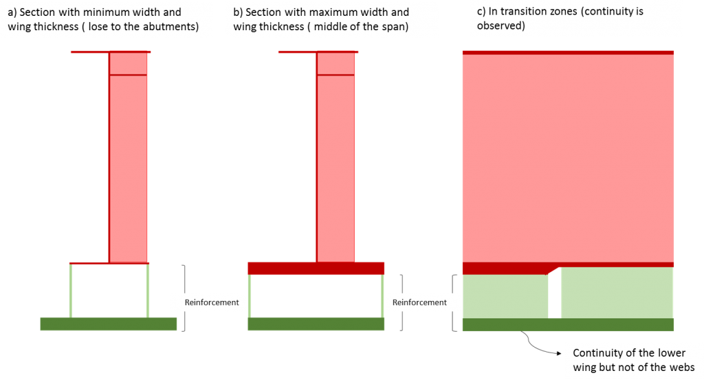
Figure 4. Design of the proposed reinforcement. Diagrams. Cross section with minimum dimensions of the lower wing of the beam [a)], same for maximum dimensions [b)] and resolution of the discontinuity of the wing [c)].
The proposed design guarantees the continuity of the lower wing – mainly responsible for the inertia contribution -, the adaptability to the geometry – through the discontinuity of the web – and minimises the number of complex welding operations to be carried out – especially ceiling welding.
The dimensioning of the reinforcement was carried out by optimising the design through the definition of the edge of the webs and the thickness of the lower flange of the reinforcement and by considering the thickness of the web and the lower flange of the reinforcement as constant.
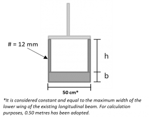
Figure 5. Variables for the design of the reinforcement.
The optimization of the section was designed to achieve the best compromise solution between:
- Compliance with the AASHTO design regulations for the method of service loads and allowable stresses.
- Minimum amount of steel required.
- Minimum increase in the edge of the longitudinal beams (avoiding a significant reduction in the clearance)
- Maximum inertia
- Ensure the feasibility to implement it on site (workability)
According to the results of the simulations based on the combinations of loads, as well as the different coefficients to be applied as indicated in section 3.22.1A of the AASHTO Standard for the load groups I, II, III and VII defined therein, the most unfavourable combination was in the middle of the span, reaching 146% of the admissible stresses according to the applicable AASHTO regulations.
Considering this scenario, using the Digital Twin, three reinforcement alternatives were designed and simulated and analysed together with the null option, i.e. no reinforcement was implemented
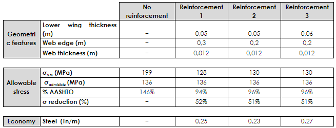
Table 1. Results obtained for the different proposals for reinforcement in the most unfavourable situation for the structure, Group I (M). According to AASTHO regulations and quantity of steel required per linear metre.
As can be seen in the table above, the best alternative taking into account both the design criteria according to regulations and the economic criteria turned out to be Reinforcement 2. The implementation of this reinforcement would allow for a reduction in stress of 51% with respect to the current situation for the most unfavourable load scenario, i.e. Group I (M).
Below is a sketch of Reinforcement 2 with the minimum dimensions required by calculation:
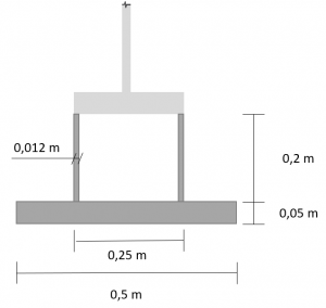
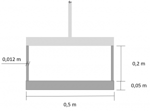
Figure 6. Minimum dimensions required by calculation for the selected reinforcement. Sections close to the supports (left) and section in the middle of the span (right)
As far as the construction process is concerned, the joints between the different elements would be made by butt welding with prior edge preparation in the workshop, as indicated in the respective sections of the Manual de Carreteras de Chile and AASHTO Standard.
In order to avoid imperfections associated with the execution ‘in situ’, the greatest number of welding operations would be carried out in the workshop prior to installation. If developed, the future project of reinforcement should contemplate the breakdown of the elements that compose it and what joints should be made previously in the workshop.
As the total length of the bridge exceeds 30 metres, the reinforcement should be assembled on site in sections to be determined according to the means of transport considered. It is recommended that these sections coincide with the discontinuities of the webs of the reinforcement to avoid inducing residual stresses in the reinforcement during assembly.
Furthermore, in no case should two welded seams coincide at a single point (avoiding three-dimensional joints), since the simplicity of the reinforcement design allows this type of joint to be avoided.
Finally, to ensure the reliability of the approach, the integrity of all the structural elements of the bridge (slab, longitudinal beams, vertical triangulations, horizontal triangulations and diaphragms) was also checked once the aforementioned reinforcement was incorporated, according to the load combinations considered (Load Groups I, II, III and VII defined in section 3.22.1A of the AASHTO Standard).
Conclusions
After verifying that the Calle Calle Bridge is currently in an acceptable condition (i.e. there is no condition that could produce the collapse at present), an Advanced Structural Diagnosis was carried out consisting of the simulation of highly demand scenarios. Based on the results of the latter, we used the Digital Twin for the optimum design of a reinforcement of the structure.
The chosen reinforcement results in a 51% reduction of stresses in the middle of the span for the worst case scenario [Group I (M)] according to the AASHTO design standard.
By simulating the influence of this increase in inertia and therefore in the stiffness of the longitudinal beams, it was found that there was indeed a reduction in the maximum stresses in all the load groups and all the structural elements. The benefit obtained, in accordance with the evaluation criterion based on the AASHTO, is translated into a reduction of more than 70% in the most favourable cases (for example, in Group VII (II) for the diaphragm or concrete crossbeams).
In addition to the compliance of the longitudinal beams with the regulations, the diaphragm or concrete crossbeams located in the supports does not exceed the stresses admitted by the regulations and the stress demand on the rest of the elements of the structure has been significantly reduced.
For this reason, we can conclude that the incorporation of a reinforcement with the specified dimensions and characteristics would imply an increase in the resistant capacity of the structure – especially in the central span area – and a decrease in the maximum stresses in a generalised way in all the structural elements.
Thus, we can guarantee that, thanks to the reinforcement, the section in the middle of the span of the structure complies with current design criteria, adapting it to the regulations in force in Chile.
The use of the Digital Twin created for the diagnosis of structural health has allowed the dimensioning of the reinforcement (U-shaped, box-type reinforcement, with a web edge of 0.2 m and a wing thickness of less than 0.05 m). Our methodology allows to achieving a compromise between compliance with the AASHTO design regulations for the method of service loads and allowable stresses, the minimum amount of steel required, the minimum edge increase of the longitudinal beams and the maximum inertia.
References
AASHTO (2002). Standard Specifications for Highway Bridges.2002
AASHTO (2007). LRFD Bridge Design Specifications.
Instituto Nacional de Normalización de Chile (2007). NCh 430-2007: Hormigón armado — Requisitos de diseño y cálculo.
MINCIENCIA – Ministerio de Ciencia, Tecnología, Conocimiento e Innovación (2020). Proceso de participación para contribuir con la Política Nacional de Inteligencia Artificial. Recuperado de http://www.minciencia.gob.cl/politicaIA
Vialidad (2012) Estudio de definición de cargas especiales de sobrepeso para el Puente Chacao. Ministerio de Obras Públicas, Gobierno de Chile.
Vialidad (2018). Manual de Carreteras (Volumen 3). Instrucciones y Criterios de Diseño
Zecchin, E., Marchesini, O., Traversaro, J. C., & Clariá, J. J. (2015). Proyecto de refuerzo del puente sobre el arroyo Paranay-Guazú–Estudio de caso. Revista de la Facultad de Ciencias Exactas, Físicas y Naturales, 2(2), 45-50.